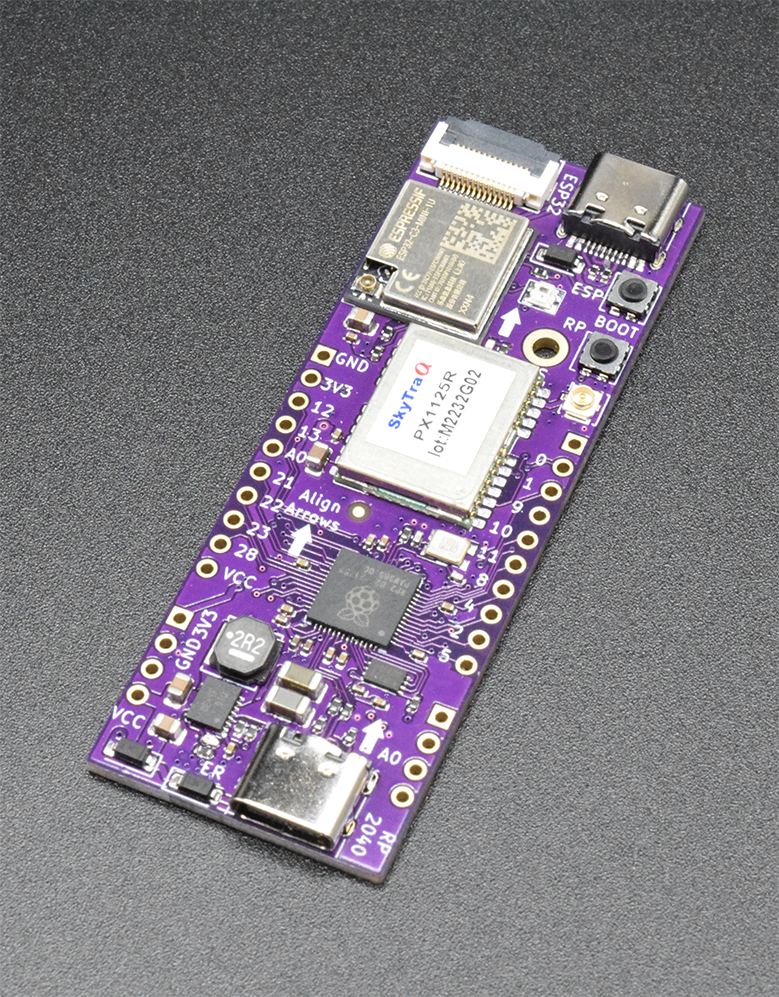
TinkerNav serves as the base board for the TinkerRTK family. TinkerNav includes a PX1125R/PX1122R GNSS receiver and RTK engine, an RP2040, and an ESP32-C3. Interfaces include GPIO pin breakouts, USB-C connectors to the RP2040 and ESP32-C3, a flat ribbon cable connector to an SPI driven display, and antennas for the ESP32-C3 and PX1125R.
Hardware
The RP2040 interfaces with the PX1125R/PX1122R GNSS receivers and ESP32-C3 WiFi and BlueTooth radio. The RP2040 also controls the optional SPI display, TinkerSend LoRa or mobile radios, and TinkerCharge board for connecting and charging a battery. You can use the ESP32-C3 to send or receive RTK correction data to or from an internet source with a WiFi or BlueTooth connection. The ESP32-C3 can also connect to another TinkerNav using WiFi or a direct connection to send or receiver correction data. If additional range is needed, or the base station and rover are not connected to WiFi, use the the TinkerSend LoRa or Mobile radios. Our Sending RTK Corrections page describes the options in more detail and links to example software.
TinkerNav Pinout
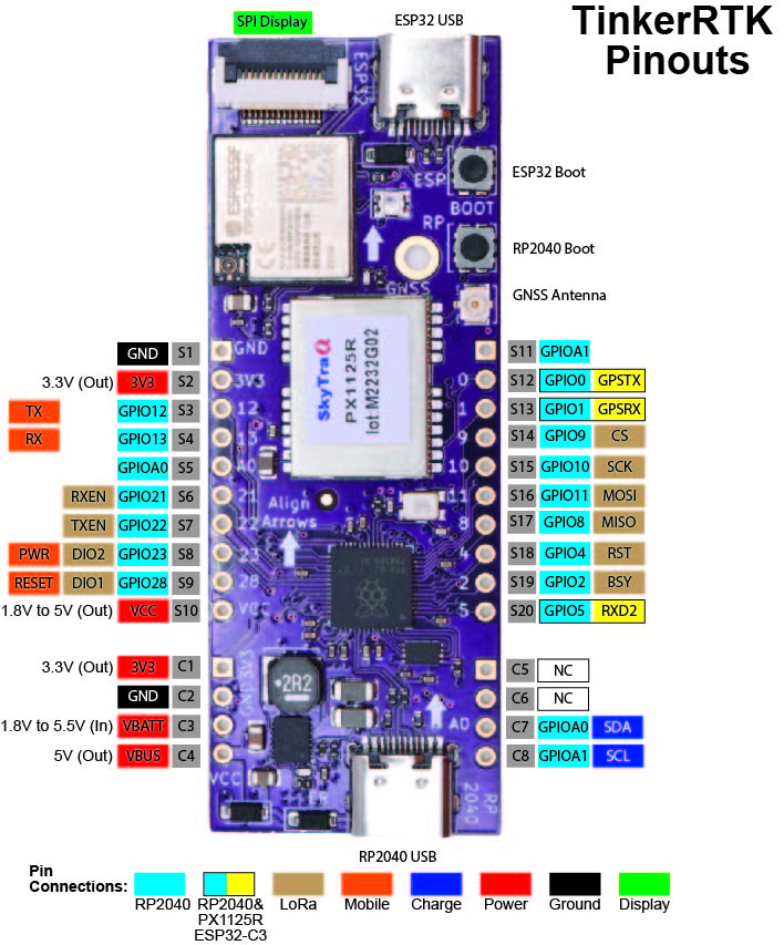
The TinkerNav base board includes connections to TinkerCharge and the TinkerSend boards. The pinout figure shows which RP2040 pins are broken out and what they are used for on the TinkerSend and TinkerCharge boards. The ESP32 has a hardware serial connection to the PX1125R/PX1122R transmit pin (to receive GNSS data) as well as the RXD2 (to send RTCM correction data to the receiver). Hardware serial connections provide less data loss and higher speeds for these two critical functions. Software serial can also be used for a bi-directional connection to the PX1125R/PX1122R. Finally, the ESP32 is also connected to the RP2040 using two pins that can be used to transmit data between the processors using a serial data connection.
Power
TinkerNav is powered by either of the USB-C connections, or the C3 VBATT pin. The VBATT pin accepts voltages from 1.8 to 5.5V. You can apply power to any or all of the three sources at the same time. Diodes are used to prevent power feedback from one source to the other and automatically ‘select’ the best power source to feed through the Buck converter. VBUS is an output pin and supplies power directly from one or both of the USB-C connections when it is present. The S10 VCC pin comes after the diodes and is not intended to be used to supply power to the board. The S11 3V3 pin comes after the Buck converter and should never be used to supply power to TinkerNav. S10 and S11 are outputs intended to provide power to the optional TinkerSend boards.
Input voltage on VBATT can range from 1.8V to 5.5V. VBUS is connected to the USB-C power line and is usually 5V, but could also range from 1.8V to 5.5V. The RT6154A Buck Boost converter produces 3.3V regardless of the input voltage. This range of voltage allows you to power TinkerNav from a USB source, or a single cell Li-ion battery. The RT6154A produces up to 3 amps of power to power the PX1125R/PX1122R, RP2040, ESP32-C3, optional LCD screen, and optional TinkerSend-LoRa radio. The TinkerSend-Mobile is powered from the S10 VCC pin and has its own RT6154A Buck converter since it requires a 2 amp power supply of its own.
"S" GPIO Breakouts
The “S” pins break out GPIOs from the RP2040 and provide power to the TinkerSend boards. The GPIO numbers map to the Raspberry Pi’s GP pins on their Pico pinout diagram. The Pico diagram is also used to understand what functions each available GPIO pin provides. The radio side connections are included in the pinout diagram above. Most of these RP2040 GPIO connections are available for other uses if you are not using a TinkerSend radio. The exceptions are the following pins that are shared:
- S12 GPIO0 – PX1125R/PX1122R TX pin
- S13 GPIO1 – PX1125R/PX1122R RX pin
- S20 GPIO5 – PX1125R/PX1122R RXD2 pin (correction data)
- S2 GPIOA1 – TinkerCharge SCL
- S5 GPIOA0 – TinkerCharge SDA
Note that if you are not using the TinkerCharge board, then the S2 and S5 pins can be used for any purpose as well, such as connecting I2C sensors.
"C" GPIO Breakouts
The “C” pins are used to connect to the optional TinkerCharge board or can be used to power TinkerNav following the instructions in the “Power” section above. C7 is shared with S5 and connections to the GPIOA0 SDA pin on the RP2040. C8 is shared with the GPIOA1 SCL pin on the RP2040. Note that VBATT is an input and VBUS is an output.
Plug-in Boards
The RTKNav board has two sets of 2.54mm sockets, one pair of 1X4 and one pair of 1X10. The TinkerSend radios, LoRa and Mobile, plug into the set of 1X10 pins. The TinkerCharge board plugs into the set of 1X4 sockets.
When plugging in board it is important to align the arrows on the board with the arrows on the TinkerNav board. The arrows should point towards to the top of the board. Plugging boards in backwards should not result in damage, but they will not function.
More details on TinkerSend-LoRa, TinkerSend-Mobile, and TinkerCharge are available at these links.
Schematic and KiCad Files
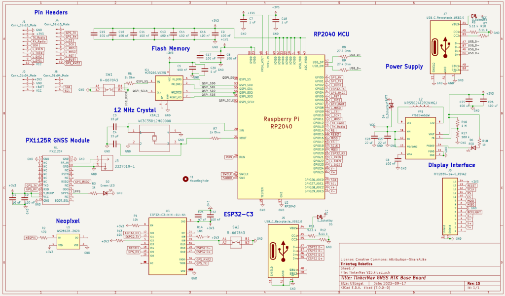
Schematic files for the TinkerNav board are available in KiCad format and available at our GitHub page. Schematics are licensed with the Creative Commons-Share Alike license.
Software and Programming
Tutorials of several common use cases are provided in the “Getting Started” menu from our homepage. Open source software examples are provide at our GitHub repository.
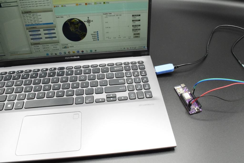
The PX1125R/PX1122R receivers are programed from the RP2040 in our software examples, which ensures the receivers are configured correctly for the use case at hand. However, you can also use NavSpark’s GNSS viewer to visualize GNSS data from the PX1122R/PX1125R or to change settings on the receiver manually. You can use a USB to TTL serial cable such as this one from AdaFruit. The red power cable connects to VBATT, the black ground cable to GND, the green cable to GPIO0, and the white cable to GPIO1. The GNSS viewer software should recognize the input and suggest a serial speed to use. The PX1125R will come flashed with a speed of 115200. AdaFruit and others provide instructions for adding or updating drivers if your cable is not recognized by your computer. Instructions on using the GNSS viewer are found on NavSpark’s site.
Programming the RP2040
The USB-C connection at the bottom of the board with the RP2040 label on its right is used to program the RP2040 from any computer. You can program the RP2040 using any of the techniques used for a Raspberry Pico. TinkerNav will appear like a Raspberry Pico because it uses the same hardware as the Pico. Pico supports MicroPython, a C/C++ SDK, and the Arduino IDE. Raspberry Pi includes documentation on using MicroPython and the C/C++ SDK. All three methods work well, but our software uses the Arduino IDE and MBED Pico board since there are many existing libraries and a larger user base for the Arduino environment. Many good tutorials and videos exist to get you set started using the Pico with the Arduino IDE, one good example is this one. We have tested our software with the Arduino 1.8.x IDE since the Arduino 2.0 IDE still had some compatibility issues when we started development.
Once you are able to flash basic programs to the TinkNav’s RP2040 you can then move on to flashing any of the software we have built for different configurations our TinkerRTK boards. Note that if you get an error flashing the RP2040 or it does not appear in the Arduino IDE you can hold the “Boot” button above the GNSS antenna and it will appear as a mass storage device and can be uploaded to from the Arduino IDE or other method
Programming the ESP32-C3
The USB-C connection at the top of the board to the right of the flat ribbon cable display connector is used to program the ESP32-C3. Our software for the ESP32 uses the Arduino 1.8.x IDE. To program the ESP32-C3 with the Arduino IDE you first have to install ESP32 board set, one good tutorial on the subject is here. The correct board for the ESP32-C3 is “ESP32C3 Dev Module” and is near the top of the list of boards after you select “ESP32 Arduino”. Once you have the correct board selected you can flash your program to the ESP32-C3. Our repositories include software to directly connect ESP32 modules to send/receive correction data and to connect to internet based correction services. The ESP32 can also be used to connect to a device, such as a phone, using Bluetooth.
Note that if the ESP32-C3 does not respond you can reset it by holding down the “Boot” button below the ESP32-C3 USB-C connector and press and release the “EN” button to the right of the ESP32-C3 module.
Plug-in Boards
The RTKNav board has two sets of 2.54mm sockets, one pair of 1X4 and one pair of 1X10. The TinkerSend radios, LoRa and Mobile, plug into the set of 1X10 pins. The TinkerCharge board plugs into the set of 1X4 sockets.
When plugging in board it is important to align the arrows on the board with the arrows on the TinkerNav board. The arrows should point towards to the top of the board. Plugging boards in backwards should not result in damage, but they will not function.
More details on TinkerSend-LoRa, TinkerSend-Mobile, and TinkerCharge are available at these links.