For a rover without a reliable connection to a WiFi network or the ability to connect to a base station using LoRa can use the TinkerSend – Mobile 3G/4G SIM7000 based radio to connect to an NTRIP caster on the internet (either public or private). The NTRIP caster can be a publicly available caster (either free or paid) or can be your own NTRIP Caster. RTK2Go.com is an example of a publicly available caster. If you live near a current provider of data to RTK2Go, you may not need to operate your own base station at all (skip to the rover configuration in this case). If you are not near enough a correction source, you can provide data to RTK2Go using a base station connected to a WiFi network or <provide data to RTK2Go using a second TinkerNav board with TinkerSend mobile.> A private caster is one that you operate yourself. Advantages of a private caster include additional data available to debug configuration issues.
In this example we will use a TinkerNav base station providing data to a SNIP based caster hosted on a local windows machine. The base station uses WiFi to send data to our SNIP based caster. The rover uses TinkerSend – Mobile and a 3G/4G network to connect to our caster and retrieve correction data to ultimately compute an RTK solution.
WiFi Base Station Configuration
- 1 TinkerNav base board
- 1 2.4 gHz WiFi antenna (provided with the TinkerNav boards)
- 1 GNSS antenna
- WiFi network for the base station
Hardware
PX1125R/PX1122R Configuration
The GNSS receiver is configured during the setup portion of the example programs by sending binary messages to the receiver from the RP2040. Specifically, the programs find the current baud rate of the receiver and resets it to factory defaults. The RP2040 firmware then sends another binary message to the PX1122R/PX1125R instructing it to operate as a survey in base station. Optionally, you can also configure TinkerNav using SkyTraq’s GNSS viewer, using our instructions.
RP2040 Firmware
Since we are using a WiFi basestation the firmware comes from the TinkerNav WiFi NTRIP Project. Flash the program in the RP2040 base station directory in the GitHub project to the RP2040 on the TinkerNav. The Arduino IDE is used to flash the firmware since it is a readily available environment with a large user base and many useful libraries. The Arduino 1.8.X and 2.X IDEs can both be used for development and flashing. Remember to use the Earle Philhower RP2040 board set. Installation instructions are found in the documentation for the board set.
The firmware is responsible for programming the GNSS receiver, reading data from a TinkerCharge board, if present, and communicating that information the ESP32, which does most of the work in this configuration.
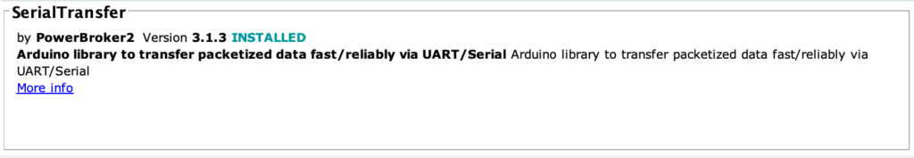
The RP2040 firmware depends on three libraries that must install, SerialTransfer, Max17055_TR, and programSkyTraq. The first of these is installed using the Arduino IDE’s Manage Libraries function, which you access from the Arduino IDE’s Tools menu. The image below show the correct library, which you can find by searching for their names in the library manager.
The second library, programSkyTaq is available from our GitHub programSkyTraq repository. Download, unpack, and copy the programSkyTraq directory to your arduino/libraries folder.
The third library, MAX17055_TR, is available at from our GitHub MAX17055_TR repository. Download, unpack, and copy the MAX17055_TR directory to your arduino/libraries folder. This library implements more functionality of the MAX17055 than the other available MAX17055 libraries. Note that even if you are not using the TinkerCharge board you will need this software, the software operates with or without the board present.
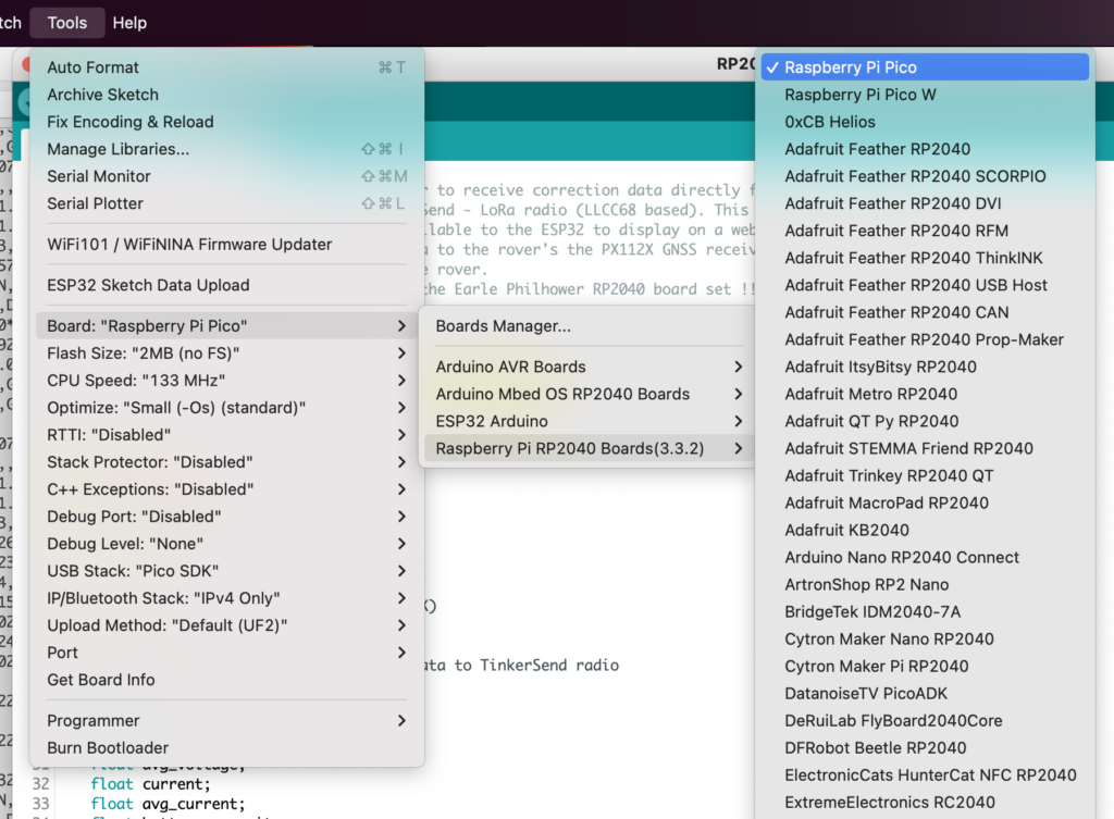
With the libraries installed, you can now compile the RP2040 firmware in the Arduino IDE and flash it to the RP2040 by connecting a USB-C cable from the computer running the Arduino IDE to the RP2040 side of the TinkerNav board. You will need to select the “Raspberry Pi Pico” board from the available RP2040 boards as shown heres
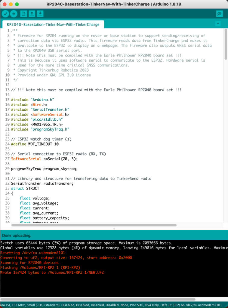
A successful flash looks like the picture below. Note that if you run into trouble flashing the RP2040 see the trouble shooting section below.
The RP2040 serial output should show it detecting the correct baud rate to talk to the PX1125R/PX1122R GNSS sensor and then show periodic updates of battery parameters sent to the ESP32. If no TinkerCharge and battery are present the data is not important.
ESP32 Firmware
In this use case, the ESP32 is responsible for connecting to the NTRIP caster to upload correction data. Grab the files in the ESP32 NTRIP Server Base Station directory to use for the ESP32. First modify the inputs.h file to point to the caster you wish to use. In this example we are using an SNIP NTRIP caster running on a windows machine on our network for testing. The inputs.h file looks like this:
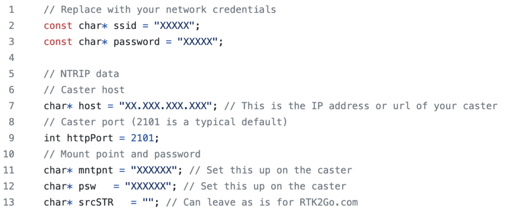
The ssid and password for your WiFi network allow the ESP32 to connect to your network and get access to the internet.
The “host” value for your NTRIP caster is your the internal IP address for the computer running SNIP. You can find this using an IP scanner.
The “mntpnt” and “psw” are the mount point name and password you set up in SNIP. SNIP provides a series of helpful getting started articles that goes over the configuration of SNIP.
Next we will flash the ESP32 on the TinkerNav base board. To flash programs to the ESP32s you need to install the ESP32 board set in the Arduino IDE. A good tutorial on installing the ESP32 board set is found here.
The base station ESP32 board is responsible for serving RTCM correction data to an NTRIP caster. To do this the ESP32 reads the RTCM correction output of the GNSS receiver and sends it to a caster. This method enables one base station to support multiple rovers. The base station’s ESP32 also serves a webpage that displays basic information about the base station’s status.
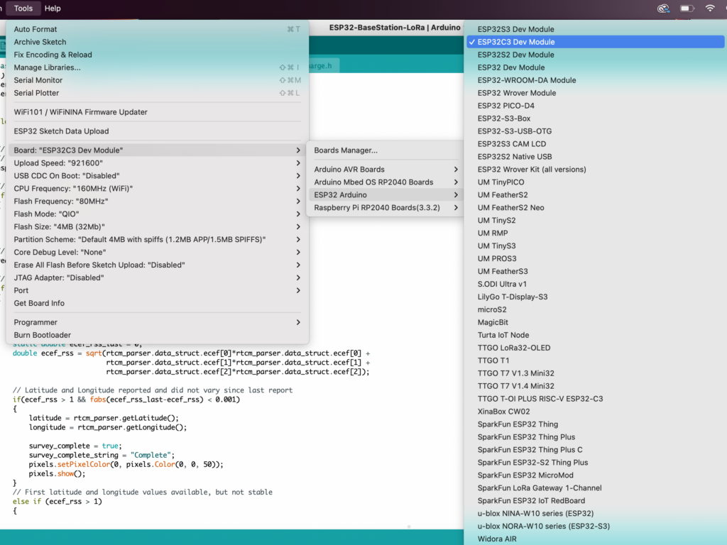
To flash the firmware select the “ESP32C3 Dev Module” board from the “ESP 32 Arduino” board set.
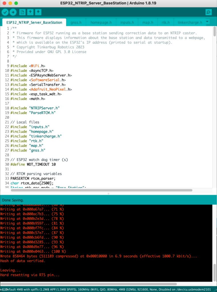
A successful flash will look like this:
Running the program attached to a serial monitor should show something like the following output in the serial viewer:
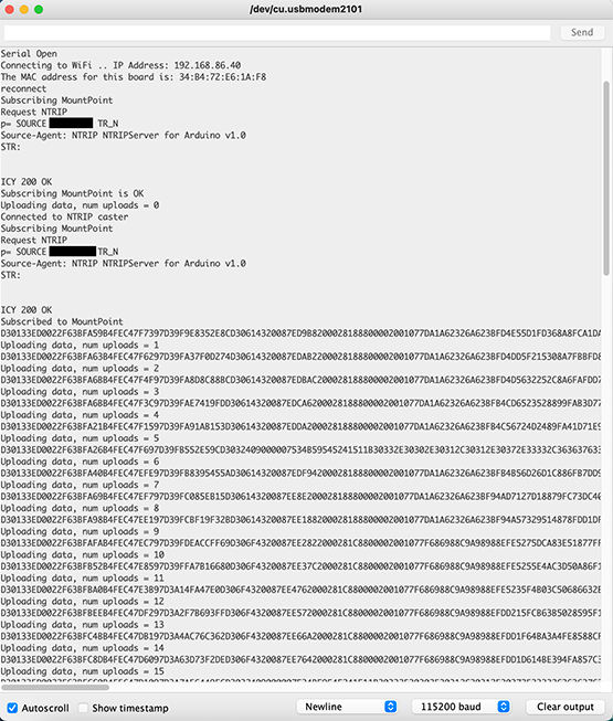
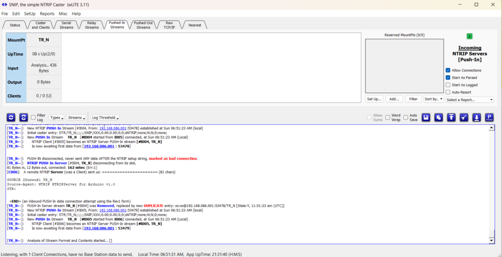
The ESP32 connects to your network, connects to the caster, and then periodically sends correction data (RTCM) messages to your caster. You should also now be able to run your TinkerNav base station and see it appear in the SNIP “Pushed In Streams” tab, similar to the image below.
Congratulations, you have a working base station and are half way there!
TinkerSend – Mobile 3G/4G Rover Configuration
Next it is time to configure the rover. In this use case the rover uses the TinkerSend – Mobile 3G/4G radio to connect to an NTRIP caster from anywhere there is mobile service. The SIM7000 connects to an NTRIP caster over the internet, using a mobile network, and receives RTCM correction data from a base station that also connects to the internet (as described above). For the rover you will need:
- 1 TinkerNav base board
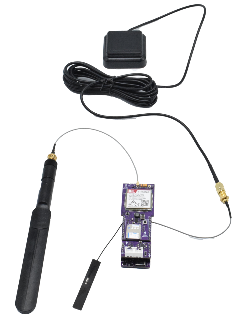
- 1 GNSS antenna
- 1 TinkerSend – Mobile board
- 1 3G/4G antenna (included with TinkerSend – Mobile)
- 1 SIM card with data for a network with service in your area, examples include tello or hologram
- (optional for debugging) 1 2.4 gHz WiFi antenna
- (optional) Tinkercharge board
Hardware
Connect the GNSS antenna to the U.FL connector on the TinkerNav board. See the TinkerNav pinout for location of the GNSS antenna. Optionally connect the 2.4 gHz patch antenna to the ESP32 MHF3 (smaller) connector. WiFi can be used for debugging, but is not used during operation since it is assumed the rover will not be able to connect to a WiFi network during operations.
Plug the TinkerSend – Mobile board into the two 10 pin slots on the TinkerNav board. Be careful to align the arrows on both boards and ensure all 10 pins are connected to avoid damage to the boards. The TinkerSend – Mobile radio should extend over the GNSS antenna connector. If you are using it, plug the TinkerCharge board into the two 4 pin slots. Again, ensure you align the arrows and that all pins connect. The battery and solar connectors should be on the edge of the board.
Once you have double checked all physical connections, power the rover through one of the USB C ports or through the battery connector on the optional TinkerCharge.
Reminder to position your GNSS antennas outside and ideally away from buildings and trees. Placing a piece of metal a few inches bigger than the antenna under the antennas helps reduce multi-path and improve antenna performance. The metal can be as simple as a sheet of aluminum foil.
PX1125R/PX1122R Configuration
The GNSS receiver is configured during the setup portion of the example programs by sending binary messages to the receiver from the RP2040. Specifically, the programs find the current baud rate of the receiver and resets it to factory defaults. The factory defaults are the correct configuration for our rover. Optionally, you can also configure TinkerNav using SkyTraq’s GNSS viewer, using our instructions.
RP2040 Firmware
The RP2040 firmware is available in our GitHub repository. The firmware is tested using the SNIP caster; you can use either RTK2Go.com as a public caster or host a SNIP caster running on a local windows machine. Modify the inputs.h file in the folder with the .ino file to include the correct details for your caster, account, etc. Specifically, “host” is the IP address of your caster. If you are using RTK2Go.com, use 3.143.243.81. Currently the software does not resolve domain names, so you need to use the IP address. If you are hosting your own caster, use a service like whatismyip.com to get the external IP address of the network you are running on and use that. Next, “http_port” is the port on your caster. RTK2Go.com uses 2101 and this is also the default for SNIP, but you can modify it if you choose. “mount_point” is the name of the base station that is providing correction data to your caster, you set this up above in the ESP32 base station section. Make sure the “mount_point” value here matches the base station’s. “user” is the user name you use on the caster service; similarly “psw” is your password for the caster service. “src_string” is typically left blank. “apn” is the APN value for your mobile provider for the sim card you insert into the TinkerSend – Mobile radio. We have used both tello, with the APN “wholesale”, and Hologram, with the APN “hologram”. Finally, you can set the SIM7000 baud rate if you chose. A value of 19200 is the default and is fast enough while also not resulting in a large number of software serial errors. The image below shows the input file in the Arduino editor.

The RP2040 firmware depends on fs.h (part of the ESP32 board set install), littleFS.h (part of the arduino-pico board set install), SoftwareSerial (part of the arduino-pico board set install), programSkyTraq – available on our GitHub, AT_NTRIP – also available from our GitHub. AT_NTRIP in turn uses TR_SIM7000, which is a custom library for SIM7000 functionality available from our GitHub.
Copy and unpack the AT_NTRIP, TR_SIM7000, and programSkyTraq libraries from their respective GitHub locations into the Arduino libraries folder, this makes them available to use in the RP2040 sketch. Note also that, at the time of writing this tutorial, there is not a software serial option for the Pico-MBED board set. This is the primary reason the arduino-pico board is used.
Once all dependencies are installed, flash the RP2040 firmware to the RP2040. The RP2040 will now use the TinkerSend-Mobile to retrieve correction data from the caster you selected and feed it to the PX1125R/PX1122R. A succesfull run looks similar to the one below:

The RP2040 uses several sets of AT commands to prepare the SIM7000 to ultimately receive RTCM correction data. Details of the commands are found in the AT_NTRIP and TR_SIM7000 libraries. At a high level the following steps occur:
- The first steps setup the PX1125R/PX1122R GNSS receivers by finding the current baud rate used by the GNSS receiver and sending it a message to reset to factory defaults, which is the correct configuration for this example.
- Next the RP2040 looks in its file system to find the current SIM7000 baud rate. This can be set by the user in the inputs.h file and is remembered by the SIM7000, so stored and looked up by the RP2040 so it matches the SIM7000.
- Next the RP2040 power cycles the TinkerSend-Mobile SIM7000 to restart and turn it on, waiting for the expected response from the SIM7000.
- After turning on the SIM7000, the RP2040 checks to see if a SIM card is available.
- Next the RP2040 sets the proper mode for mobile network. Note that this may be different for different networks and thus need to be changed in the software if not using Tello or Hologram.
- Next all existing connections are closed to put the radio in the proper initial state.
- Signal strength is checked, and printed periodically until it is greater than 0. This ensures the SIM7000 is properly connected before moving on.
- The next several steps attach the SIM7000 to the provider’s network. First setting the providers APN value, then opening the connection and checking the IP address and network registration status before moving on.
- The next steps are NTRIP caster specific and may need to be changed in the libraries if using a caster other than a SNIP caster. First a connection to the caster is established by sending a specific command to it over a TCP connection, then once the connection is established an initial request is made for NTRIP data.
- Once the NTRIP data request is properly acknowledged, the caster should send NTRIP correction data as it is available. The RP2040 will read that data from the SIM7000 and both send it to the GNSS receiver’s correction port and print the numbers of the messages received to the USB serial for debugging/awareness.