This setup uses the built in ESP32 radios on the TinkerNav boards to transmit correction data between base station and rover and enable an RTK solution on the rover. See our How to Send Correction Data page for additional information on options for sending correction data between base station and rover.
Required Components
This is the most basic setup for running your own base station and rover and requires:
- 2 TinkerNav base boards
- 2 GNSS antennas
Setup
For this setup you will have a rover and a base station communicating directly using a WiFi soft access point setup on the base station. The hardware is the same for the rover and base station with different firmware and configurations of the PX1105R. To start let’s set up the hardware.
Hardware
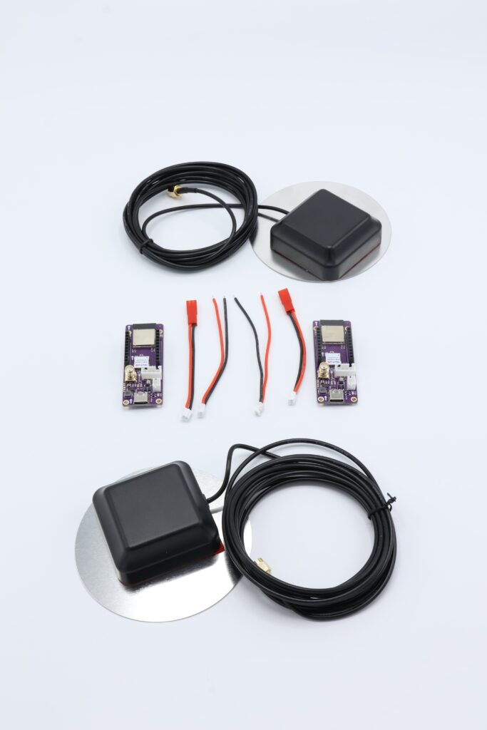
For the rover, connect the GNSS antenna to the SMA connector on the TinkerNav board. See the TinkerNav pinout for location of the GNSS antenna. Repeat this setup for the base station setup. Your setup should look something like this picture above. Power both the base station and the rover through one of the USB C ports on each or connect to a 1S or 2S LiPo battery using the provided connector.
Reminder to position your GNSS antennas outside and ideally away from buildings and trees. Placing a piece of metal a few inches bigger than the antenna under the antennas helps reduce multi-path and improve antenna performance. The metal can be as simple as a sheet of aluminum foil. Our GNSS antennas come with a metal ground plane.
PX1105R Configuration
The GNSS receiver is configured during the setup/initialization portion of the example programs by sending binary messages to the receiver from the ESP32-S3. There is no additional configuration required for the receiver. Optionally, you can configure TinkerNav using SkyTraq’s GNSS viewer, using our instructions.
Firmware
Next you will need to upload (flash) firmware to the ESP32-S3 on each of the TinkerNav boards. The ESP32-S3 in this setup interfaces with the PX1105R and also publishes it to a webpage with status information.
The Arduino IDE is used to flash the firmware since it is a readily available environment with a large user base and many useful libraries. The Arduino 1.8.X and 2.X IDEs can both be used for development and flashing.
The firmware depends on libraries from the Arduino library manager, such as AdaFruit’s NeoPixel library as well as libraries in our GitHub for creating the web page on the rover and for programing the SkyTraq receiver on both the rover and base station. Use Arduino’s Library Manager from the Arduino IDE to install the external dependencies.
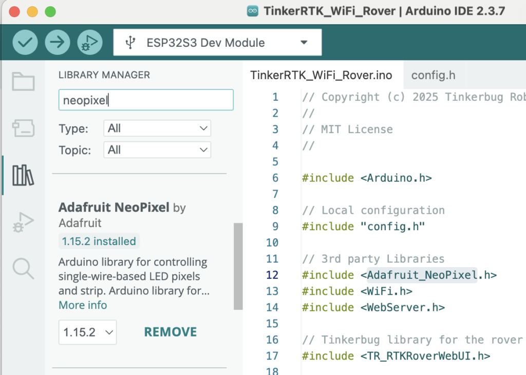
For Tinker Robotics libraries download a copy from our GitHub repository. Download, unpack, and copy the library directory to your arduino/libraries folder.
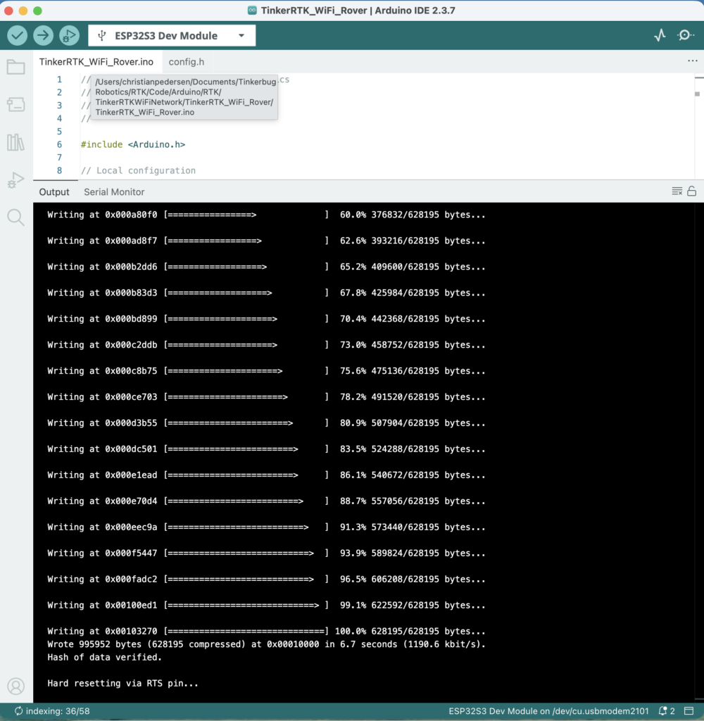
Once you have all the dependencies in place, download and open the rover sketch from our WiFi example. Connect your computer to the TinkerNav board using a USB-C cable and flash the firmware. A successful flash looks like the picture below.
Repeat the above steps for both the base and rover boards with the appropriate firmware. The base board includes “BaseStation” in the name and the rover includes “Rover” in the name.
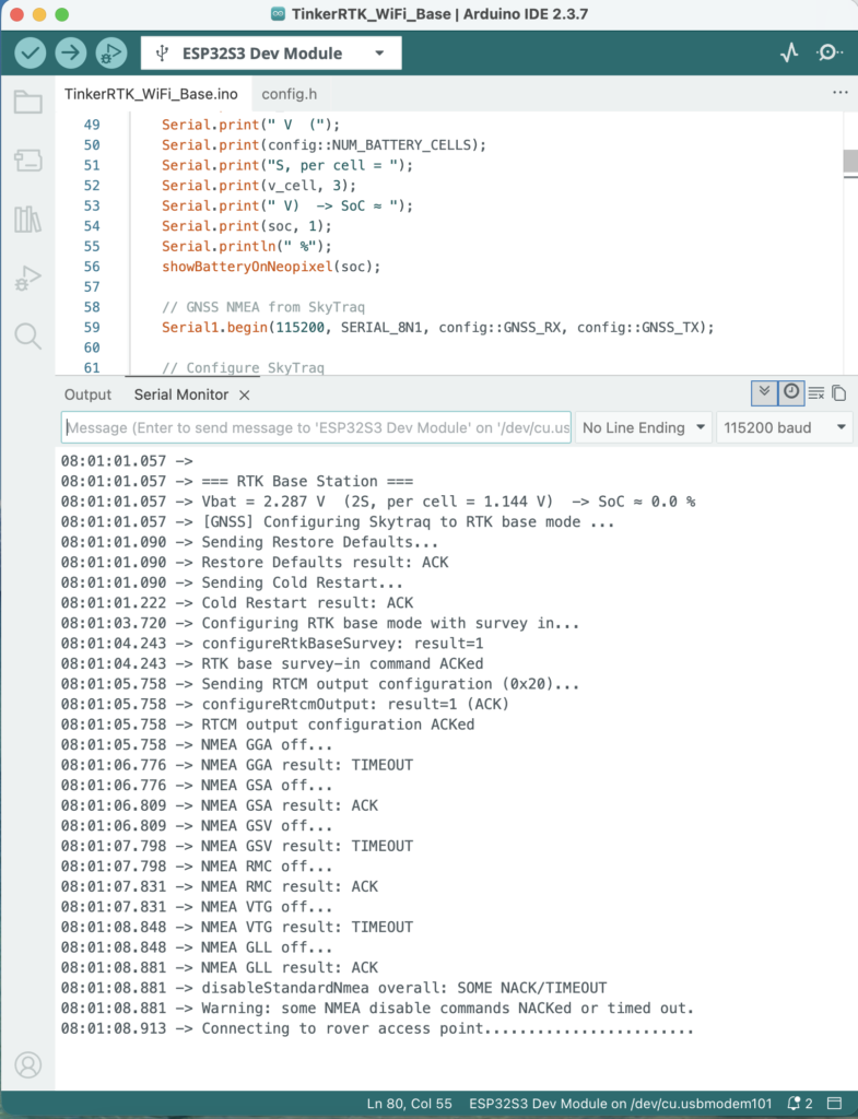
Serial output from the ESP32-S3 should look similar to this. There are a series of configuration commands sent to the PX1105R. Depending on the state of the receiver at the time the commands are sent there may be some NACKs from the receiver, but as long as some commands are successful it indicates good communication. Commands are NACKed for several reasons, one of which is that the receiver is already in the requested configuration.
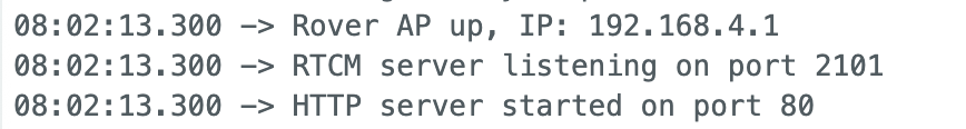
The rover serial output will include its IP address. We will use this in the next step to connect to the rover and view its webpage from any WiFi enabled device, e.g. a computer or a phone.
Working Base Station and Rover Pair
The first indication that that the boards are working as planned is the indicator light on the rover. On the rover, the light will start off red, turn to yellow when a GPS solution is found, green for an RTK float solution, and blue for an RTK fix solution. Note that it is normal for surveying to take a few minutes and the light may toggle from green to blue a few times before locking in on blue. On both the rover and the base station there is also a small blue led near the GNSS receiver that will flash once per second once a GNSS solution is found. On the base station the light will indicate battery strength by default, but the serial output from the base station should show packets of data being sent to the rover. Before a fix is achieved those packets are around 25 bytes, growing to 200-1000 bytes once a fix is achieved.
The rover also publishes a web page to the IP address it printed to the Arduino IDE serial monitor when it started up, typically 192.168.4.1. To see this page use any WiFi enabled device and connect it to the rover’s soft access point. The soft access point looks like any other WiFi network to your device. By default this access point is called tinkerbug_rover with password Tinkerbug, both can be changed in the sketch’s config.h file for additional security.
Rover
The rover webpage provides information on the current state of the RTK solution and satellites in view. The cards at the top show the current GNSS fix and RTK mode as well as the latitude, longitude, and altitude of the fix (redacted here). The cards in the second row show the RTK age, which is the age of the last successful RTK solution in the receiver and the RTK ratio, which ranges from 0 to 10, with higher values indicating a more stable RTK fix. The card on the right in the second row shows the status of the RTCM link, showing the age of the last transmit and the number of bytes last received.
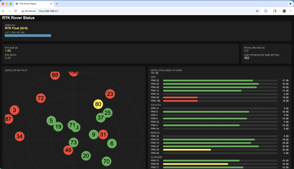
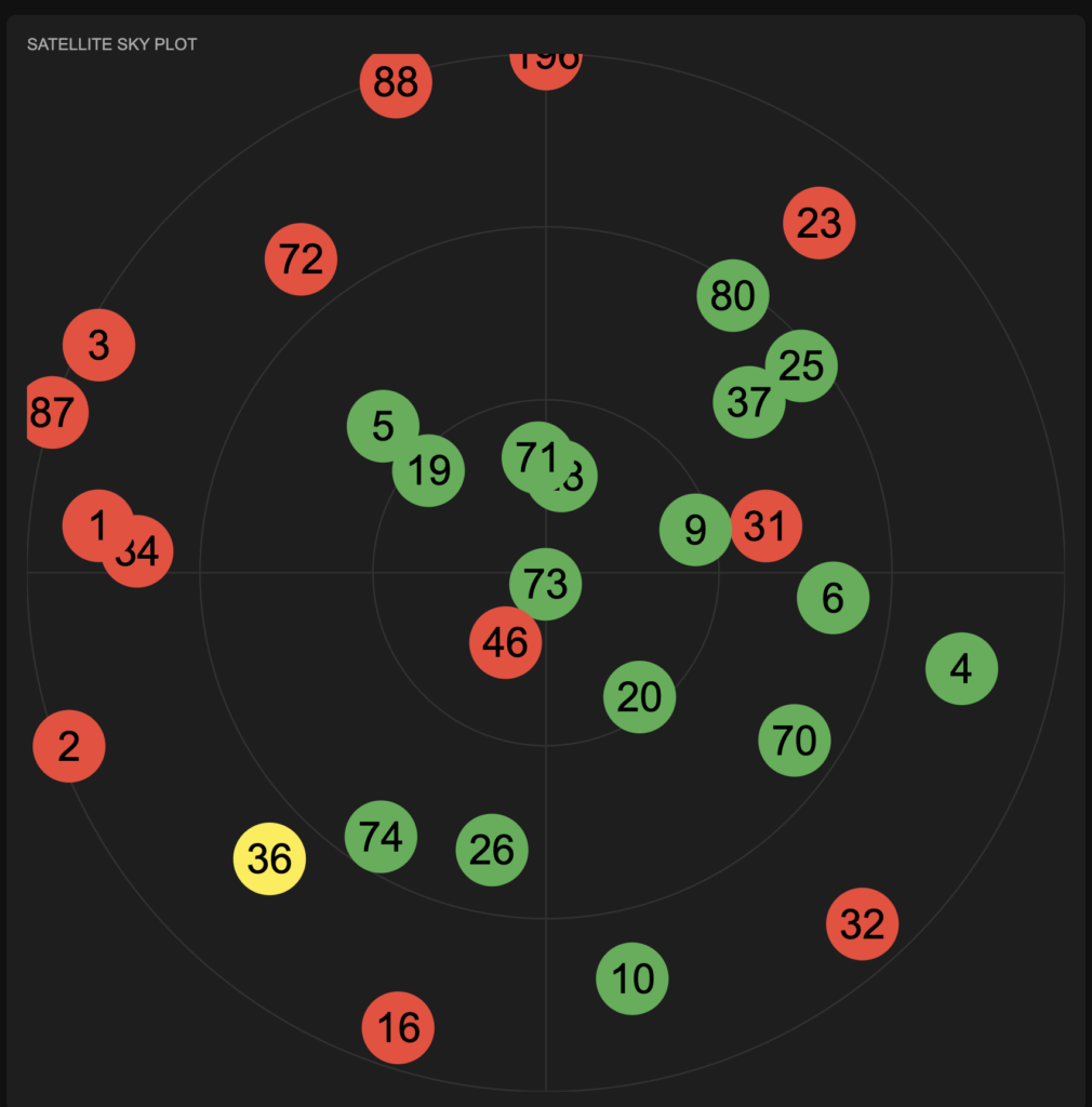
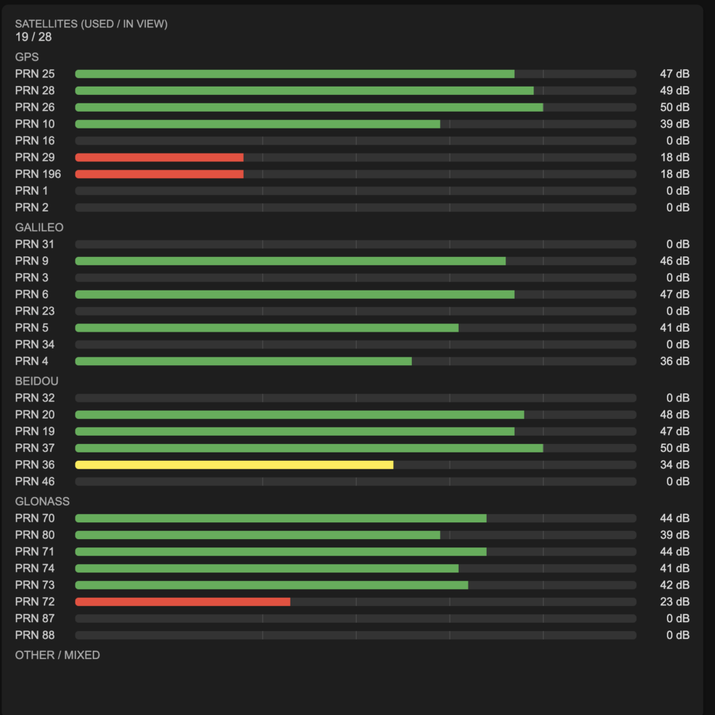
Below the status cards there are two displays showing which satellites are being used for the current fix and where they are located. First the map on the left shows the location each satellite in view. Their PRN number is shown on the circle and the strength of the signal from that satellite is shown by the color of the circle. The axes of the plot are azimuth and elevation. Azimuth aligns to the compass directions, with North up. The elevation ranges from horizon at the outermost ring to straight above in the center.
Additional signal strength data is shown in the other plot with the specific SNR for each satellite shown.
Trouble Shooting
Difficulty Detecting or Flashing the ESP32
If your ESP32-S3 processor gets in a bad state and does not respond to the Arduino IDE you can re-establish communications with the Arduino IDE by following these steps:
- Connect one end of a USB-C cord to TinkerNav.
- While the other end of the USB-C cord is unplugged, press the “Boot” button on the TinkerNav board.
- Plug the USB-C cable into your computer while holding down “Boot”
- Release the “Boot” button.
No Serial Output from ESP32, or only crash reports
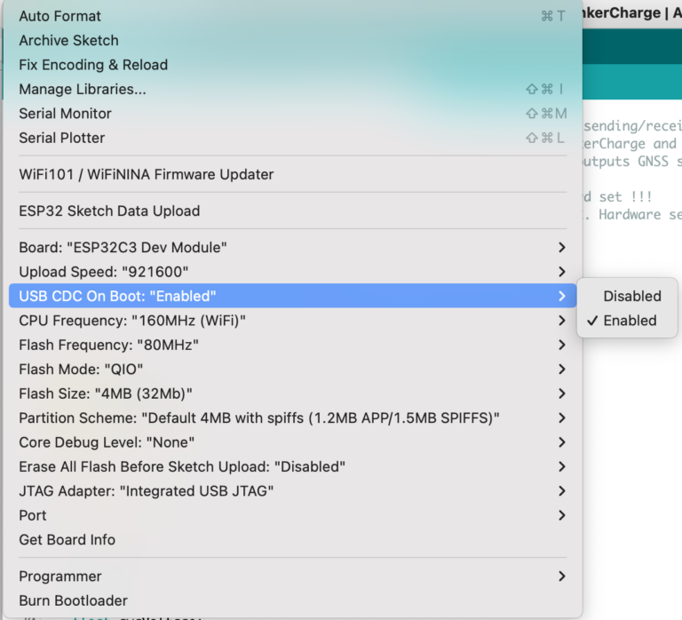
For the ESP32, if you can flash normally and the program seems to be working but you are not seeing serial output to the Arduino display you may need to enable “USB CDC on Boot”. To do this select the “Tools” menu in the Arduino IDE and select “Enabled” next to the “USB CDC On Boot:” menu item. This setting usually sticks after it is changed once, but may be lost occasionally and need to be reset to “enabled”.
Serial data is output on a crash/reset of the ESP-32 regardless of the “USB CDC on Boot” option, so there may situations where you only see these crash reports and none of the serial output you expect. Check the “USB CDC on Boot” option and make sure it is enabled.