TinkerRTK is a set of modular open source boards and accompanying open source software to enable Real Time Kinetic (RTK) GNSS for a variety of uses. Whether using TinkerNav with the built in WiFi radio or the optional TinkerSend LoRa radio, our hardware and software make it easy to get 1 centimeter accuracy in your next project. Our RTK explainer describes what RTK is, here will describe the TinkerRTK family of products.
Modular Architecture
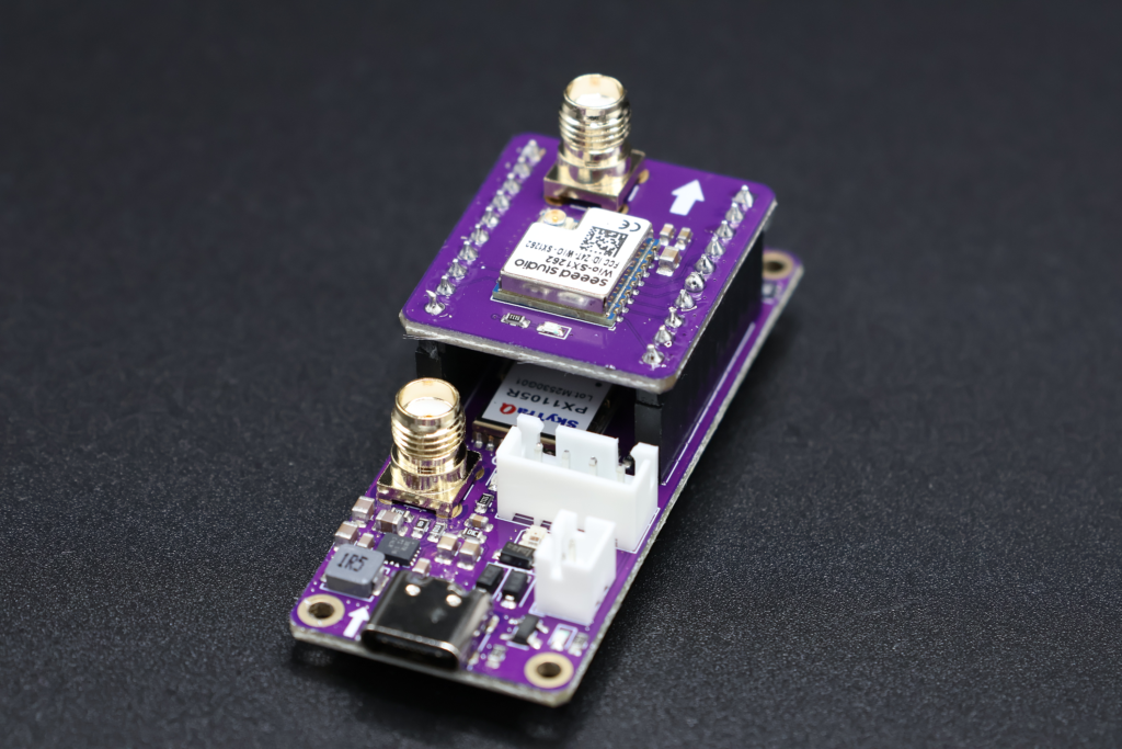
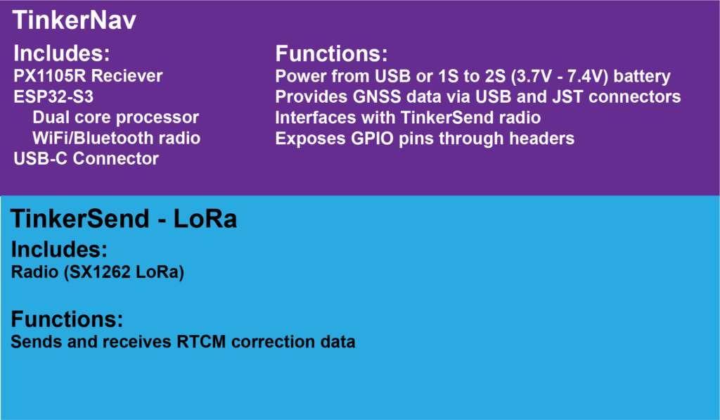
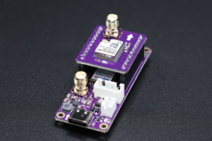
Tinker RTK includes two boards that plug together and the option of creating your own boards. The base TinkerNav board includes a GNSS receiver and an ESP32-S3 dual core processor plus WiFi/Bluetooth LE radio. A separate board is available for a LoRa radio to allow maximum flexibility in selecting the right components for your project. Our How to Send RTK Corrections page describes different options supported by the built in ESP32-S3 and LoRa radio. The diagram below describes what each of the core components of TinkerRTK do.
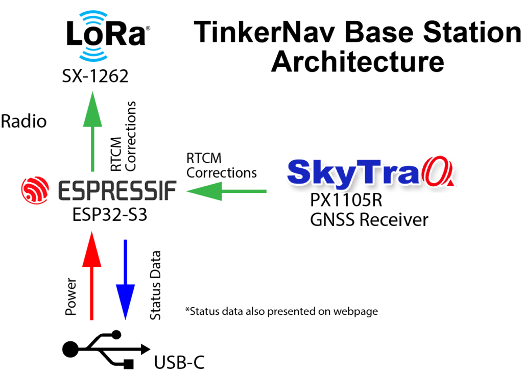
The diagrams below show how the components of the TinkerRTK system interact to compute and use corrected GNSS data in both a rover and base station configurations. In the rover configuration RTCM correction messages are received from either the ESP32 or the TinkerSend LoRa radio and sent to the RXD2 port on the receiver. The SkyTraq PX1105R GNSS receiver uses the RTCM correction data to compute an RTK solution. The data from the receiver is sent directly to the JST connector, to GPIO pins on the header, and to the ESP32. The ESP32 sends the solution to the USB-C port if desired (via configuring the firmware). The ESP32 also presents the PX1105R data to a website using the ESP32 WiFi capability.

When acting as a base station the TinkerRTK system computes RTCM corrections using the PX1105R receiver and transmits those corrections using the built in ESP32 or an optional TinkerSend radio. You can send data directly to a rover or using one of the other methods described on our How to Send RTK Corrections page. The ESP32 also publishes status information to a webpage, viewable on any device that can receive WiFi.
TinkerRTK Options
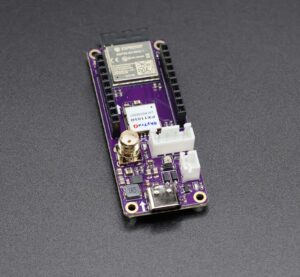
Using the modular architecture you can select the right components for your project. Starting from the base TinkerNav board that provides an RTK GNSS receiver, and ESP32-S3 WiFi/Bluetooth radio, you can add a TinkerSend -LoRa radio for longer range. See our page on how to send RTK corrections to help pick the right radio for you.
Electrical Interface
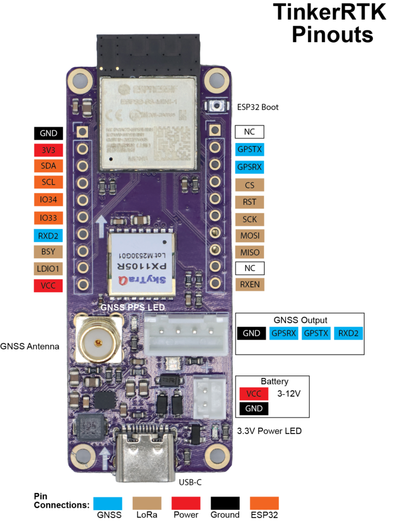
The pinout figure shows the functions of the pins that are broken out. The ESP32 has hardware serial connections to the PX1105R transmit pin (to configure the GNSS and receive data from it) as well as the RXD2 (to send RTCM correction data to the receiver in rover mode). Hardware serial connections provide less data loss and higher speeds for these two critical functions. TinkerNav is powered by the USB-C connection, or the JH 2.0 battery connection. The battery connection accepts voltages from 2V to 16V, though 1S or 2S batteries are recommended. You can apply power to the USB and battery at the same time. The VCC pin is intended to power piggyback boards and not supply power to TinkerNav.
Input voltage on VBATT can range from 1.8V to 5.5V. VBUS is connected to the USB-C power line and is usually 5V, but could also range from 1.8V to 5.5V. The TPS63070RNMR Buck Boost converter produces 3.3V regardless of the input voltage. The TPS63070RNMR produces up to 2 amps of power to power the PX1105R, ESP32-S3, and optional TinkerSend-LoRa radio.
Arrows on the boards must be aligned for proper function, though boards will not be destroyed by inserting them backwards.
Software
The TinkerRTK hardware provides power and flexibility for your project, but, of course, requires software. Our GitHub repositories contain the individual programs to operate TinkerNav in different configurations.
The ESP32 is can be programed in anyway you would typically program an ESP32. Detailed instructions and example software is provided for using the Arduino IDE.