
Description
Real Time Kinetic GNSS Base Board
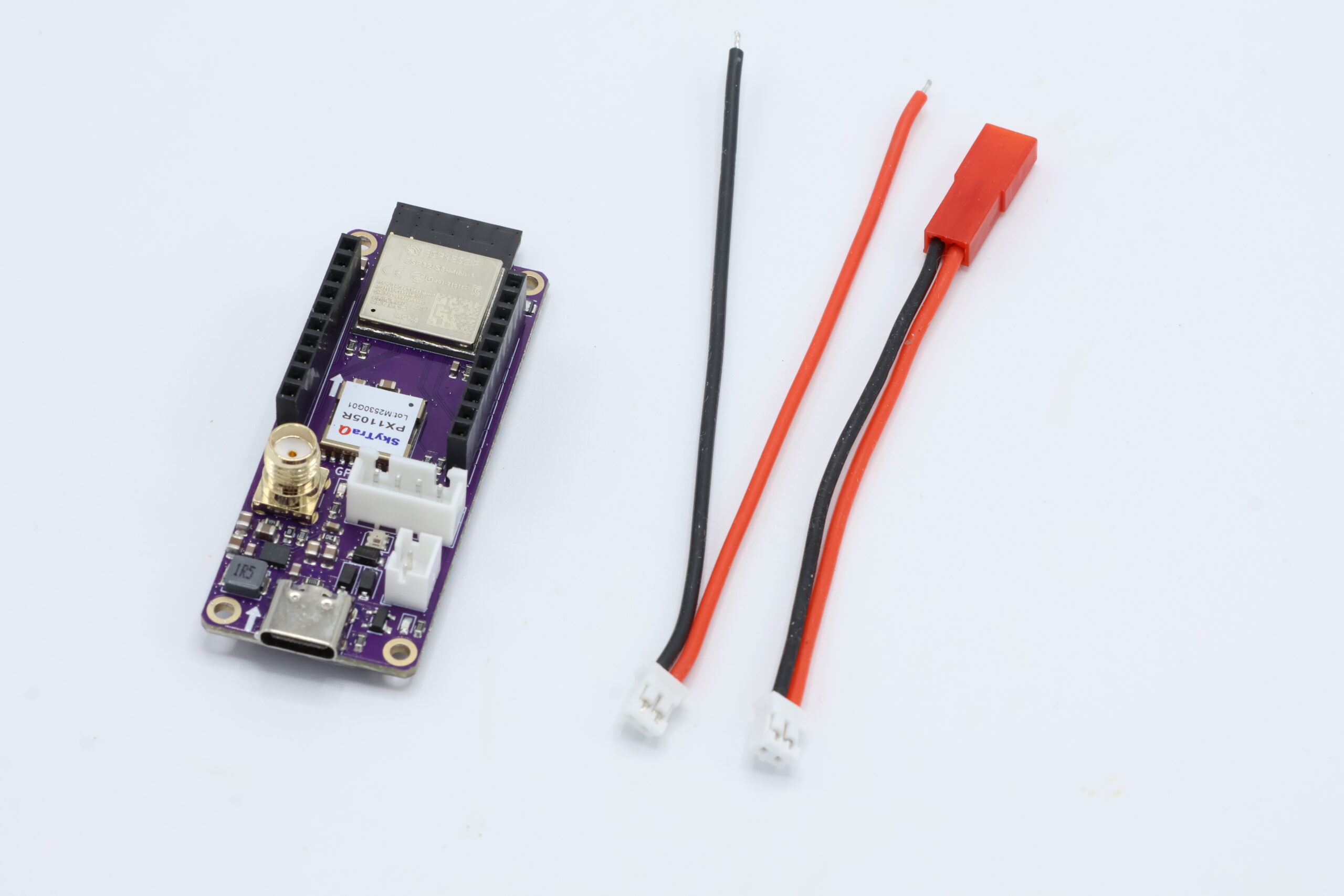
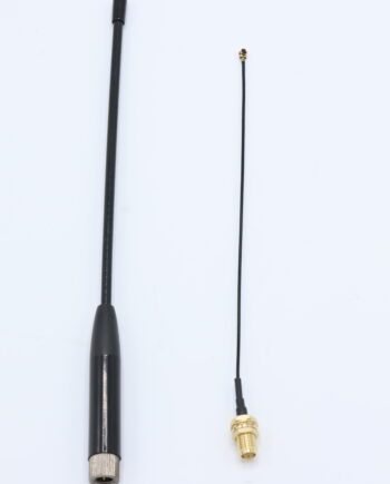
TinkerNav serves as the base station or rover in an RTK solution. TinkerNav includes a SkyTraq PX1105R GNSS receiver with built-in RTK engine and an ESP32-S3 dual core processor to run your own program (example programs included to get you started). TinkerNav also includes a variety of useful interfaces including SMA connector for an GNSS antenna, 2.54mm JST XH header for GNSS I/O, battery connection (JST 2.0 PH plus JST/BEC adapter) , and a USB-C connection for power and ESP32-S3 programming.
Included
- TinkerNav board
- JST 2.0 PH to JST/BEC LiPo adapter
- JST 2.0 PH to wire adapter
Use the built in WiFi capability or add the extended range of LoRa with our TinkerSend radio.
Hardware
The ESP32-S3 interfaces with the PX1105R GNSS receiver providing both processing and a WiFi/BlueTooth radio. The ESP32-S3 also controls the optional TinkerSend LoRa radio. You can use the ESP32-S3 to send or receive RTK correction data to or from an internet source with a WiFi or BlueTooth connection. The ESP32-S3 can also connect to another TinkerNav using WiFi or a direct connection to send or receiver correction data. If additional range is needed, or the base station and rover are not connected to WiFi, use the the TinkerSend LoRa radio. Our Sending RTK Corrections page describes the options in more detail and links to example software.

The pinout figure shows the functions of the pins that are broken out. The ESP32 has hardware serial connections to the PX1105R transmit pin (to configure the GNSS and receive data from it) as well as the RXD2 (to send RTCM correction data to the receiver in rover mode). Hardware serial connections provide less data loss and higher speeds for these two critical functions.
Power
TinkerNav is powered by the USB-C connection, or the JH 2.0 battery connection. The battery connection accepts voltages from 2V to 16V, though 1S or 2S batteries are recommended. You can apply power to the USB and battery at the same time. The VCC pin is intended to provide power to the piggy back boards and not to power TinkerNav.
Input voltage on VBATT can range from 1.8V to 5.5V. VBUS is connected to the USB-C power line and is usually 5V, but could also range from 1.8V to 5.5V. The TPS63070RNMR Buck Boost converter produces 3.3V regardless of the input voltage. The TPS63070RNMR produces up to 2 amps of power to power the PX1105R, ESP32-S3, and optional TinkerSend-LoRa radio.
LoRa and GNSS Breakouts
The orange breakouts map to ESP32 pins, but serve their listed functions for the TinkerSend – LoRa board. They can be used for other purposes with a custom piggyback board. The blue breakouts provide an additional output of GNSS data and input for RTCM correction data for custom piggy back boards.
Plugin Boards
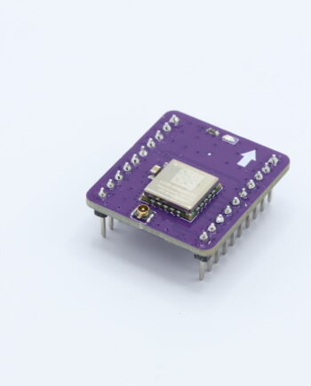
The RTKNav board has a pair of 1X10 2.54mm sockets. The TinkerSend – LoRa radio plugs in here or it can be used by custom piggy backboards.
When plugging in board it is important to align the arrows on the board with the arrows on the TinkerNav board. The arrows should point towards to the top of the board. Plugging boards in backwards should not result in damage, but they will not function.
More details on TinkerSend-LoRa.
Schematic and Kicad Files

Schematic files for the TinkerNav board are available in KiCad format and available at our GitHub page. Schematics are licensed with the Creative Commons-Share Alike license.
Modular Architecture
Tinker RTK includes two boards that plug together and the option of creating your own boards. The base TinkerNav board includes a GNSS receiver and an ESP32-S3 dual core processor plus WiFi/Bluetooth LE radio. A separate board is available for a LoRa radio to allow maximum flexibility in selecting the right components for your project. Our How to Send RTK Corrections page describes different options supported by the built in ESP32-S3 and LoRa radio. The diagram below describes what each of the core components of TinkerRTK do.

TinkerNav includes an ESP32-S3 processor and PX1105R GNSS receiver. They interact to compute and use corrected GNSS data in both a rover and base station configurations. In the rover configuration RTCM correction messages are received from either the ESP32 or the TinkerSend LoRa radio and sent to the RXD2 port on the receiver. The SkyTraq PX1105R GNSS receiver uses the RTCM correction data to compute an RTK solution. The data from the receiver is sent directly to the JST connector, to GPIO pins on the header, and to the ESP32. The ESP32 sends the solution to the USB-C port if desired (via configuring the firmware). The ESP32 also presents the PX1105R data to a website using the ESP32 WiFi capability.


Software and Programming
Tutorials of several common use cases are provided in the “Getting Started” menu from our homepage. Open source software examples are provide at our GitHub repository.
The USB-C connection at the bottom of the board is used to program the ESP32-S3 from any computer. You can program the ESP32-S3 using any of the techniques used for an ESP32. TinkerNav will appear in the Arduino IDE like a ESP32-S3 Dev Module using Espressif’s board manager. ESP32s also support the Espressif IDE.
Once you are able to flash basic programs to the ESP32-S3 you can then move on to flashing any of the software we have built for different configurations our TinkerNav board and TinkerSend – LoRa radio. Note that if you get an error flashing the ESP32-S3, or it does not appear in the Arduino IDE, you can hold the “Boot” button down while applying power to the TinkerNav and it will appear in the Arduino IDE as a device that can be uploaded to.
The PX1105R receivers are programed from the ESP32-S3 in our software examples, which ensures the receivers are configured correctly for the use case at hand. You should be able to do any programming you need from the ESP32-S3 by modifying the examples that run there and interface with the PX1105R, however, you can also use NavSpark’s GNSS viewer to visualize GNSS data from the PX1105R, change settings on the receiver manually, or update the firmware. You can use a USB to TTL serial cable such as this one from AdaFruit. Power TinkerNav from a separate USB cable or a battery and connect the USB TTL cable to the GNSS 2.54mm output. Specifically, connect the black ground cable to GND, the green cable xxx. The GNSS viewer software should recognize the input and suggest a serial speed to use. The PX1105R will come flashed with a speed of 115200. AdaFruit and others provide instructions for adding or updating drivers if your cable is not recognized by your computer. Instructions on using the GNSS viewer are found on NavSpark’s site.

Reviews
There are no reviews yet.