In order to achieve centimeter level accuracy, an RTK system needs correction data from a stationary base station. The best way to get the correction data from the base station to the rover depends on several factors. Our TinkerNav modules contain a WiFi radio in the ESP32-S3 and we offer the TinkerSend radio that uses LoRa for direct communication. In the following sections we discuss three options for sending correction data, serial modems, WiFi network radios, and WiFi direct radios.
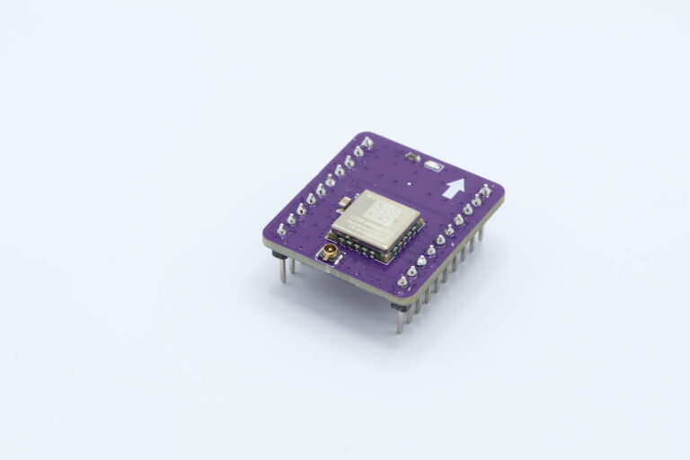
LoRa Serial Modem
If you operate your own base station and either the rover or the base station (or both) don’t have reliable access to a WiFi, then a serial modem connection is a good option for medium and long range communication. Our serial modem uses LoRa modulation and specifically a SX1262 radio by Semtech. The line of sight range for the SX1262 is over 7 km. We have tested the radio in large open fields over a kilometer with good results. The radio can also operate in a suburban environment sending signals through trees and buildings over a distance large enough to cover most lots. LoRa radios have a much lower bandwidth than WiFi radios, but it is sufficient to send RTK correction data at between 0.5 and 1 Hz. Note that your rover can operate its GNSS receiver at more than 1 Hz (such as a drone using GNSS data at 10 Hz) while using the 0.5 or 1 Hz correction data, since the correction data is a function of the atmosphere’s properties and changes little over even a few seconds.
Our system uses the ESP32-S3 processor on the main board to interact with the GPS receiver and the radio. The software is written for the Arduino IDE and is available, at our Serial Modem project on GitHub. For the base station the ESP32-S3 receives the RTCM formatted correction data from the GNSS receiver and then sends it out in packets over the LoRa radio. LoRa packets are restricted to 256 bytes by the protocol, so the ESP32-S3 breaks up the messages into packets. On the rover, the ESP32-S3 receives the packets from the LoRa radio, parses them into messages (including data spread across packets), and then sends them to the RXD2 port on the rover’s GNSS receiver. The GNSS receiver uses these RTCM messages to produce an an RTK solution with centimeter level accuracy.


WiFi Network Radio
The next option uses your local WiFi network to send data from your base station to your rover. The TinkerNav board has an ESP32-S3 WiFi radio built into the board, making this a good option for experimenting with if the area your base station and rover are operating are both covered by the same WiFi network. Here we use the popular and inexpensive ESP32 micro-controller with WiFi capability and program it using the Arduino IDE. To communicate the base station and rover set up a TCP server using the IP address of the base station ESP32 that is sending the correction data.

WiFi Direct Radio
In this option we use two ESP32 modules to communicate directly with each other. This option uses the ESP32 in both the rover and the base station TinkerNav boards, but it does not require a WiFi network, rather the radios talk directly to each other. Range is affected by the environment, but can vary from over 100 meters in the open air to less than 15 meters indoors or through walls. This is a good option for short and medium separations between base station and rover where no WiFi network is available. There are two software options here, one is very similar to the software for the WiFi network radio, except that the transmitter sets up a soft access point and the transmitter connects to that access point rather than a WiFi network. The code is available in our ESP32 repository. The second option for direct WiFi communication is to use the ESP-NOW protocol in a similar way as the LoRa Serial Modem option above uses LoRa.
Network Transport of RTCM via Internet Protocol (NTRIP)
Another method involve connecting to a network for sending RTCM correction data from a base station to a rover. NTRIP is the widely adapted protocol for sending RTCM data over a network and is based on HTTP/1.1. In order to understand the different ways to use NTRIP, let’s first look at the components of an NTRIP system. An NTRIP system has four pieces, as shown in the diagram below. First is an NTRIP Source that generates the RTCM data; in our case this is the GNSS receiver. Second an NTRIP Server ‘serves’ that data to the third piece, which is called an NTRIP Caster. Finally the fourth piece is an NTRIP Client; this is the user of the correction data. The NTRIP Caster can take input from multiple servers and provide inputs to multiple clients. The NTRIP Server software typically resides on the base station and connects the NTRIP Source (GNSS receiver) to an NTRIP Caster. NTRIP Casters are hosted on machines with a network connection, this can be in a data center on the other side of the world or on local hardware. When you subscribe to a third party correction service they will provide you access to an NTRIP Caster that you can receiver correction data from. The NTRIP Client typically resides on the rover and is the software you use to receive NTRIP correction data from an NTRIP Caster.

ESP32 to WiFi using NTRIP
In this option the ESP32 on the TinkerNav board and a WiFi network are used to connect to an NTRIP Caster publishing data to the internet. The example code uses RTK2GO, which is a freely available NTRIP caster, but it can be modified for any NTRIP Caster. You can connect to a caster as either an NTRIP server or an NTRIP client.
If an NTRIP server is available in your area for free you can use this data via WiFi and the ESP32 with the NTRIP client example. Free public sources of data vary considerably around the world. RTK2GO may provide correction data in your area, in the western united states UNAVCO has good coverage, or state and federal governments in other locations may provide correction data. There are also paid subscription services for correction data via NTRIP Casters.
